Design studies for the Royal Netherlands Navy 1939-40
By Lt. Jurrien S. Noot, Royal Netherlands Navy
Author.s note:
The information presented in the article is not intended as a full design history in narrative form of the battlecruisers once proposed to be constructed for the Royal Netherlands Navy. This would not be possible anyway because only fragmentary records appear to remain. Rather, I have tried to present the basic information found in the files of the Naval Historical Division of the Naval Staff in The Hague in an orderly form to give some understanding of the characteristics of the various designs that evolved, and to publish all the more pertinent drawings that were produced.
Due to the fact that my research had to be limited to the files of the Naval Historical Division, it is quite possible that the article does not give a complete presentation of the facts. Any person who is in possession of additional information from original records is invited to comment. I am thinking of those who may have access to the German World War II files that may contain some original data on these ships, since at the outbreak of war in May 1940, all Dutch records seem to have been requisitioned by the Germans. There is no way of knowing at present if any material was ever returned.
Editor.s note
The Dutch battlecruiser designs of 1939-40 were made known in detail first by the late R.F. Scheltema de Heere in his article .Slagkruisers voor Nederlands-Indië 1939. in Marineblad Vol. 76 No.2 (Maart 1966), pp. 127-147. Lt. Noot.s article provides a fuller documentary record of the design work and makes the story available to English language readers for the first time. Dutch naval programs of the late 1930s are also addressed in detail in L.L. von Munching.s .H.Nl.M.S. De Zeven Provincien C-802. in Warship International No.4, 1976, pp. 251-269.
Editor.s note
We thank William A. Becker for his many hours spent in tracing the many drawings used in this article.
Introduction
In 1938 A COMMITTEE consisting of high ranking naval officers was appointed to investigate various possibilities of strengthening the naval forces of the Netherlands. The main conclusion of this investigation was that the Royal Netherlands Navy would have to be strengthened in such a way that any aggressor would be forced to use such a large part of his military potential that there would be an unacceptable weakening of his capabilities in other theatres.
Within the context of this investigation, Mr. J.J.C. van Dijk, the Minister of Defence, instructed the Navy Department on 18 February 1939 to work out a plan for the construction of a heavy naval unit. This instruction was the result of a note from the Chief of Naval Staff (a copy of which has not been found) in which the construction of such a vessel had been proposed, along with the construction of a third light cruiser. However, the Minister of Defence would not allow this third light cruiser to be incorporated into the program, and stated that any proposals made would have to be within the context of the naval program currently planned. It was to be considered what possible savings could be made on the basis of either a reduction of the calibre of the main armament or a reduction in the number of guns carried. Cost estimates were to be provided for the construction of 2 or 3 battlecruisers, including an analysis of the personnel consequences, and it was to be investigated if the ships could be constructed in Dutch shipyards.
Staff requirements
The Navy Staff requirements for the proposed battlecruisers had been defined on 17 February 1939 as follows:
| Speed: |
Maximum speed in tropical waters to be 32 kts., to be sustained at least 12 hours. Acceleration from 20 kts., cruising speed to 30 kts. to possible within 15 minutes. |
| Propulsion: |
Not to be fitted with peacetime propellers, which would necessitate changing propellers during times of tension.
Well thought out engineroom subdivision, to limit possible loss of speed in case of being hit in this area.
|
| Radius: |
To be 4500 NM at 20 kts., to compare with the 1938 Light Cruiser Design |
| Heavy Artillery: |
Three 28cm triple turrets, 120 rounds per gun. Turrets to be fitted for independent firing. |
| Medium Artillery: |
Serving as anti-aircraft and anti-torpedoboat battery. Four twin 12cm mounts (as in gunboats but need not be stabilized), 120 rounds per gun, 100 starshells. All 12cm guns to be capable of independent firing. |
| Light Artillery: |
One group of three twin 40mm machineguns to be fitted forward with centralized fire control; one group of four twin 40mm mounts to be fitted aft with centralized fire control. 1000 rounds per barrel to be carried. |
| Torpedoes: |
No torpedo armament. |
| Aircraft: |
Two fighter aircraft and two reconnaissance aircraft. If possible, two catapults to be fitted (one to port and one to starboard). Hangar for at least two aircraft |
| Armor: |
(a) Excellent anti-torpedo and anti-mine protection. |
| (b) Armor in general to be able to withstand 28cm shell hits and 300kg aircraft bombs. |
| (c) Armor scheme to be as follows: |
| Main belt to extend from aft to forward turret |
250 mm |
| Remaining waterline belt | 80 mm
|
| Main armored belt | 125 mm
|
| Splinterdeck on top of armored deck | 30 mm
|
| Control tower . sides | 300 mm
|
| Control tower . roof | 150 mm
|
| 28cm turrets . barbette | 250 mm
|
| 28cm turrets . front | 300 mm
|
| 28cm turrets . roof | 150 mm
|
| 28cm turrets . sides | 100 mm
|
| 12cm mounts . barbette | 80 mm
|
| 12cm mounts . front | 80 mm
|
| 12cm mounts . roof | 125 mm
|
| 12cm mounts . to be protected against the effect of 200kg aircraft bombs and 14cm shell hits. |
| (d) Steering gear to be well protected. |
| (e) Machine guns to be mounted on armored decks and protected with 40mm splinter armor |
| (f) Anti-torpedo bulkheads extending to double bottom and to be able to absorb 53cm torpedo hits. |
| Draft: |
Deep load draft not exceeding 9 meters, preferably less. |
| Logistics: |
Supplies to last for six weeks.
60 tons fuel for Dornier aircraft.
25 tons fuel for MTBs.
100 tons aircraft fuel. |
| Complement: |
Accommodations for 50 officers, 100 non-commissioned officers, 900 ratings. |
| General: |
It was to be investigated what possible financial savings could be achieved if the main battery was reduced to six guns. |
The basic design requirements were formulated again on 21 February 1939 in a letter by the Chief of Naval Staff (copy not found), and on 22 February 1939 orally passed to the Naval Construction Department. It was estimated that the length of the ship would be about 240 meters, the beam about 29 meters and the draft about 7.50 meters, and that it need 180.000 SHP divided over 4 shafts. The Construction Department worked out a preliminary design on the basis of these requirements, which was completed on 11 July 1939 (see Table 1 for the characteristics of the design).
| Table 1 - Design characteristics: 1939 Preliminary Design dated 11 July 1939 |
| Dimensions |
| Length on DWL |
230.00m |
| Beam-max. (over armor) |
29.65m |
| Beam-max. (over frames) |
29.00m |
| Draft (trial displacement) |
7.45m |
| Molded depth (centerline) |
13.80m |
| Molded depth (sides) |
13.40m |
| Displacement |
| Washington |
26000 t |
| Trial |
26998.5T |
| Normal load |
27916.0T |
| Machinery |
| Shaft horsepower |
160000 |
| Drive |
Steam turbines |
| Boilers |
4 x 2 |
| Propellers |
4 |
| Max. speed |
33 kts. |
| Radius |
4500 NM at 20 kts. |
| Armament |
| Main armament |
9 x 28cm in triple turrets (120 rounds per gun) |
| Secondary armament |
8 x 12cm in twin turrets (200 rounds per gun) |
| Anti-aircraft armament |
14 x 40mm in twin mounts (1000 rounds per gun) |
| Various armaments |
2 catapults
2 aircraft. |
| Armor & protection |
| Vertical side belt |
250mm tapering upwards to 150mm |
| side belt |
250mm tapering upwards to 150mm and 100mm |
| side aft |
100mm |
| side forward |
100mm |
| longitudinal bulkheads |
two 30mm each side |
| main transverse bulkheads |
not indicated |
| Horizontal |
| main armored deck |
125mm |
| upper deck |
15mm |
| Artillery - 28cm turret |
| front |
300mm |
| roof |
130mm |
| sides |
100mm |
| barbette |
250mm |
| Underwater |
| double bottom depth |
1.00m |
| depth of side protective system |
7.00m |
| depth of main side belt |
6.00m (2.45m below DWL). System consisting of two longitudinal anti-torpedo bulkheads on each side. |
| Various |
2 paravanes, 3 smokemakers, 100m3 gasoline. |
| Coefficients of form |
| Block coefficient |
0.5193 |
| Midship section coefficient |
0.9617 |
| Prismatic coefficient |
0.5400 |
| Waterline coefficient |
0.6700 |
| Note: Exact particulars of this preliminary design are not clear. According to one description this would have been a two-funneled ship, but the surviving drawing of 11 July 1939 shows a one funneled ship. |
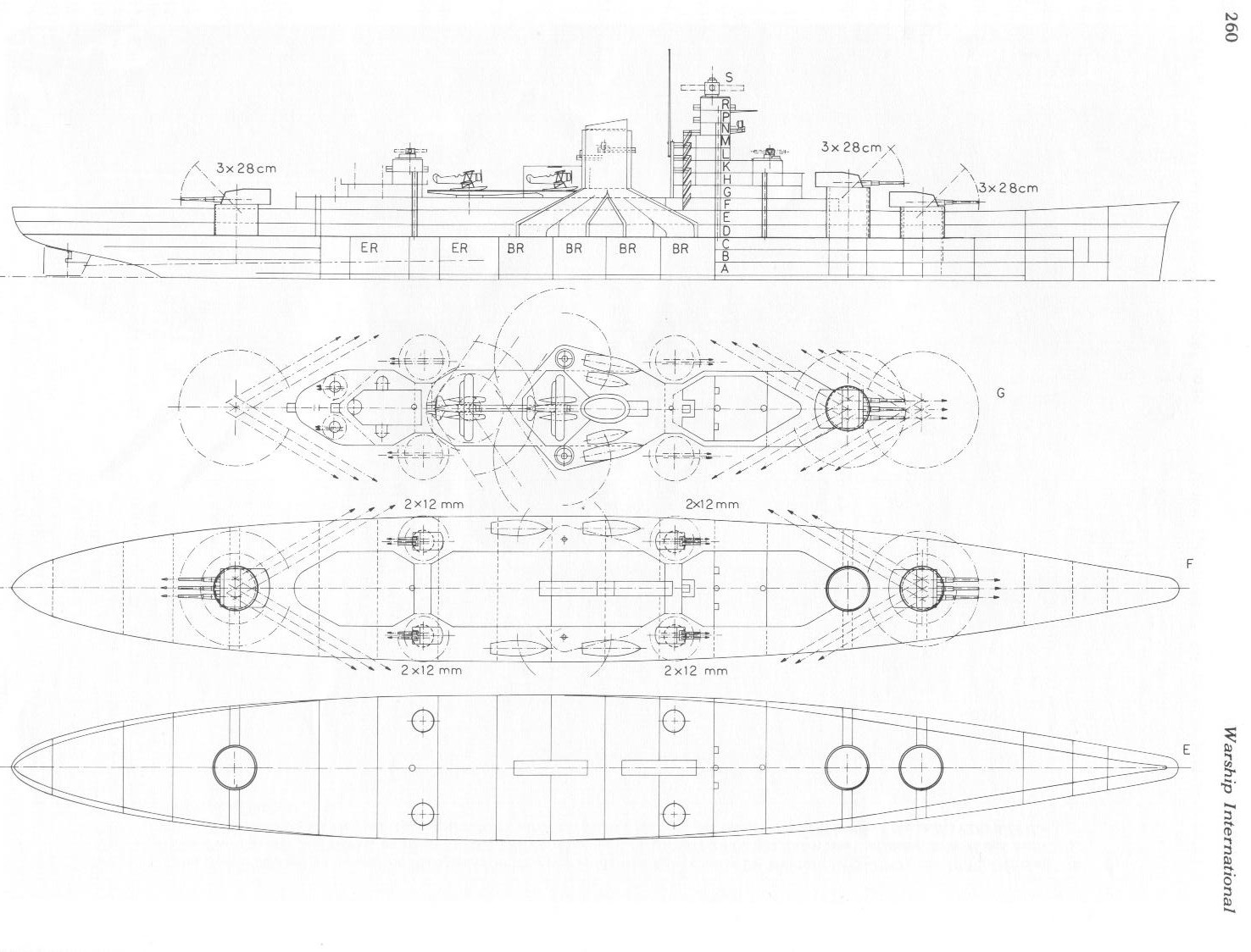 |
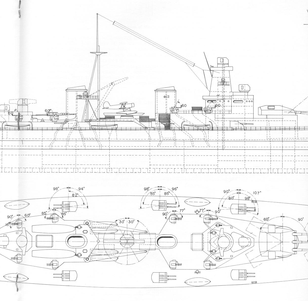
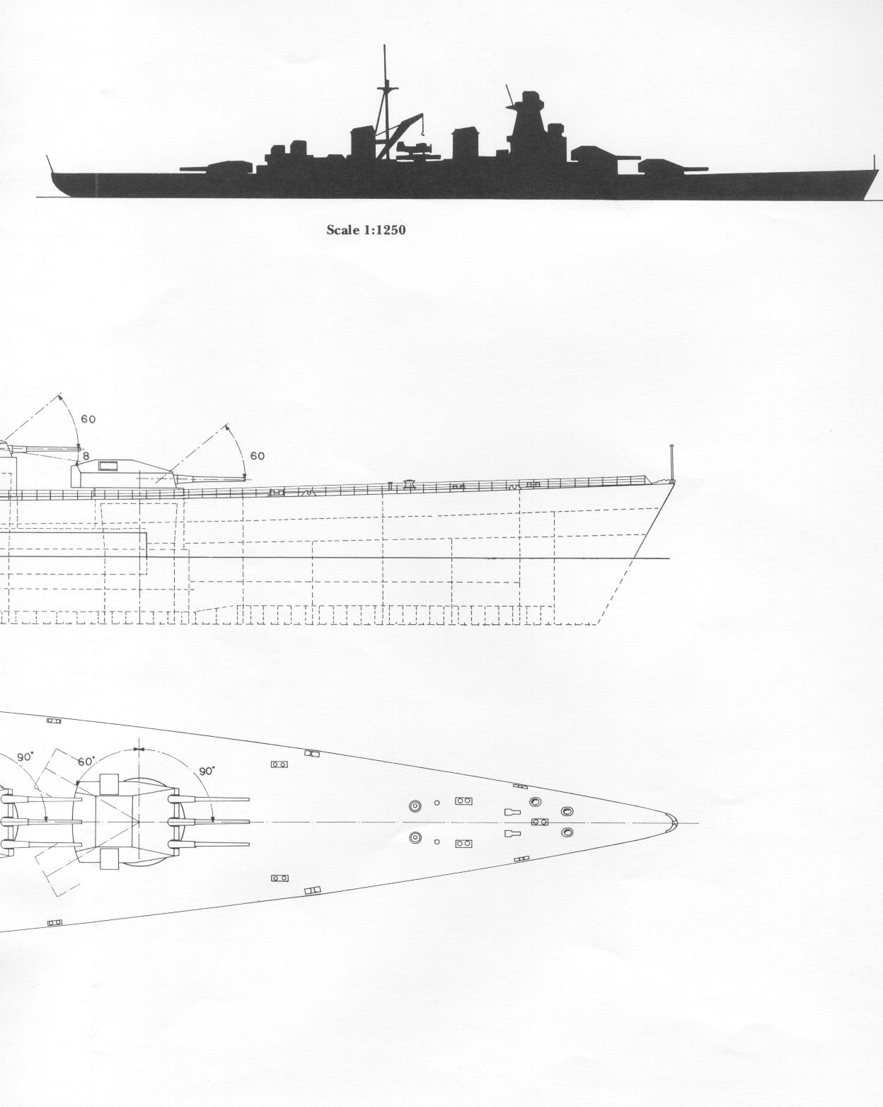
Battlecruiser Preliminary design 1939 (I) (11 July 1939)
This drawing gives an overview of armament lay-out and the ships' general profile.
(Click on the drawing on the left. The link will open a new window) |
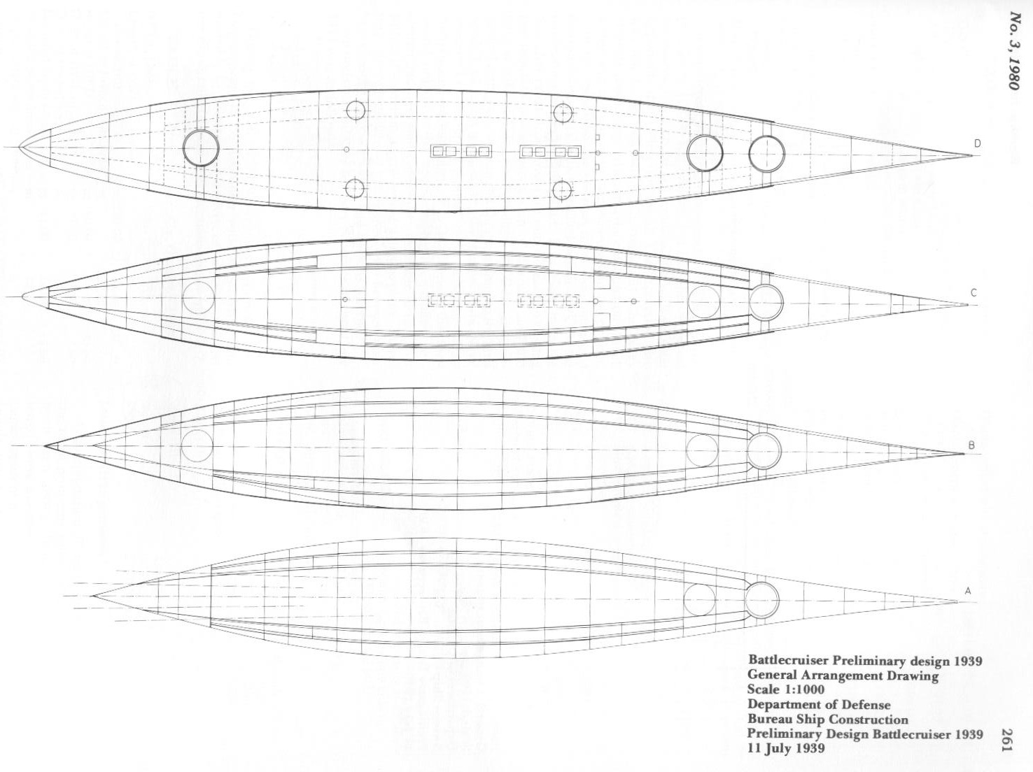 |
Battlecruiser Preliminary design 1939 (II) (11 July 1939)
This drawing gives an overview of the ships' subdivision
(Click on the drawing on the left. The link will open a new window) |
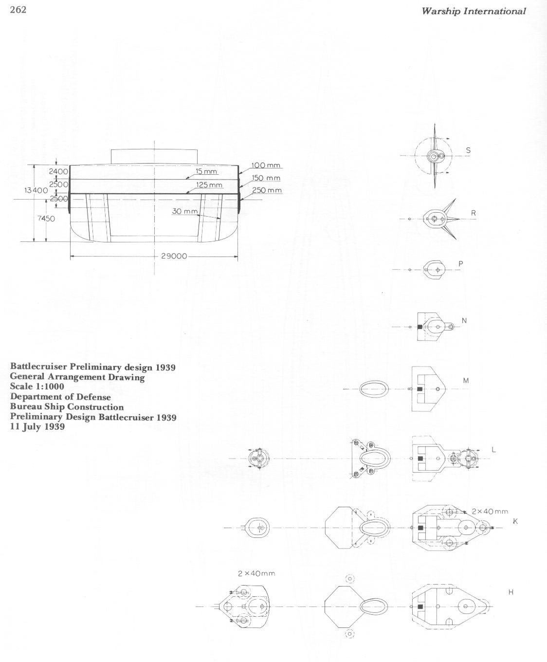 |
Battlecruiser Preliminary design 1939 (III) (11 July 1939)
This drawing gives a cross-section overview of armor distribution.
(Click on the drawing on the left. The link will open a new window) |
However, it is apparent that the Dutch naval constructors had little knowledge of the technical developments that had taken place in capital ship design subsequent to the First World War, particularly with regard to protection. Although the preliminary design featured a good horizontal protection (consisting of a 125 mm main armored deck with a 15 mm deck on top), the general arrangement and the distribution of armor resulted in a capital ship design dating 20 to 25 years back. In fact, it appears that the only useful reference material available consisted of open source literature and Jane.s Fighting Ships. It was clear that technical assistance from abroad was imperative in order to produce a suitable up-to-date design.
Although there was some hope that the French would release drawings of their Dunkerque Class battlecruisers, the Dutch authorities felt that it would be best to concentrate efforts to obtain foreign assistance to Germany, at least for the time being. So it happened that the first informal discussions with German authorities regarding the battlecruiser project occurred on 24 and 25 April 1939 in Berlin. The Dutch delegation stated that they were interested in the release of a complete German design of a Gneisenau type vessel, in return for which the necessary equipment would be ordered from Germany. It was also proposed that Dr. Techel of the .Ingenieurskantoor voor Scheepsbouw. (I.v.S.) would act as a trait d.union between the Dutch and German technicians. Although the Germans appeared to be genuinely interested in the project, they wanted guarantees that orders in Germany would actually take place if construction was to proceed, and that Germany would receive financial compensation in case the ships were not built. However, the release of the plans of the Gneisenau would be out of the question. The initial German reluctance can be attributed in part to the fact that so far the project was just that, while during the summer of 1939, the Dutch Cabinet was not convened so no political decisions of great magnitude could be taken.
In the meantime, a contact had been established with the German firm Ferrostaal A.G. Essen, and on 15 May 1939, a detailed listing of equipment to be ordered in Germany was submitted as follows:
| Equipment |
Required delivery date |
| 37,500 tons of armor |
June 1940 through January 1944 (the bulk to be delivered before January 1943) |
| 18,000 tons of construction material |
June 1940 through June 1943 (the bulk to be delivered before January 1942) |
| nine 28cm triple turrets and twelve 12cm twin mounts |
Spring 1943 through late 1943 |
| 28cm and 12cm ammunition |
Late 1943 through late 1944 |
| 6 catapults |
July 1943 through late 1944 |
| Propeller shafts |
Late 1941 through late 1943 |
| Various equipment for propulsion plant |
1940 through 1942 |
| 15,000 tons of steel to be used for the construction of a floating dry dock |
During 1942 |
During talks held in Bremen (13 July 1939) and in Berlin (31 July 1939), the Germans promised to release a design study that would incorporate their ideas on battlecruiser construction. This design study was submitted to the Royal Netherlands Navy on 21 August 1939, and showed various possible schemes of protection. Its basic characteristics are listed in Table 2.
| Table 2 - Design characteristics: German Sketch Design 21 July 1939 .Holland-Schlachtschiff. |
| Dimensions |
| Length on DWL |
227m |
| Beam |
30m |
| Draft on DWL |
8m |
| Moulded depth |
14m |
| Displacement (metric tons) |
| Hull (S I-IV) |
8000 |
| Armor & Protection (P) |
9900 |
| Main engines (M I) |
3100 |
| Aux. engines (M II) |
1000 |
| Aircraft |
80 |
| Gunnery armament |
4100 |
| Equipment |
650 |
| Water |
200 |
| Reserve |
470 |
| Type displacement |
27500 |
| Feed water & fuel oil |
2000 |
| Legend displacement (DWL) |
29500 |
| Type displacement |
27500 |
| Max fuel oil |
4600 |
| Lubricating oil, etc. |
200 |
| Feed water |
160 |
| Reserve drinking & washing water |
340 |
| Full load displacement |
33000 |
| Machinery |
| SHP |
ca. 172.000 |
| Main engines |
4 high pressure turbine sets |
| Radius |
ca. 5500 NM at 20 kts. |
| Speed (legend displacement) |
ca. 33 kts. |
| Armament |
| Armament |
9 x 28 cm in triple turrets (150 rounds per gun)
8 x 12 cm in twin turrets (200 rounds per gun)
16 x 40 mm (ammo not indicated) |
| Armor and protection |
| Vertical side belt |
225mm |
| Side aft |
60mm |
| Side forward |
30mm |
| Citadel |
60mm |
| Longitudinal side bulkheads |
30mm and 20mm |
| Citadel longitudinal bulkhead |
15mm |
| Horizontal main deck |
100 and 125mm |
| upper deck |
30 and 20 mm |
| Artillery 28cm barbette |
170mm and 225mm |
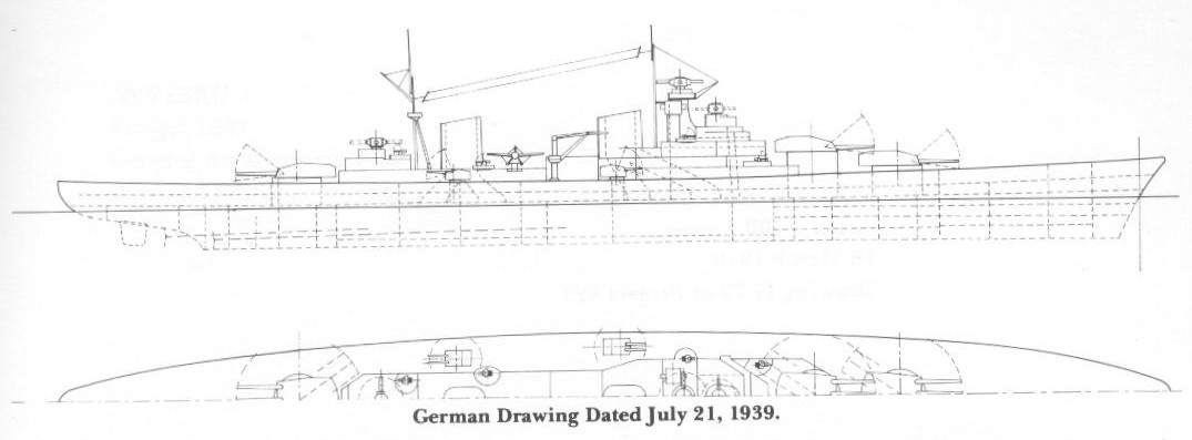 |
German profile drawing (21 July 1939)
(Click on the drawing on the left. The link will open a new window) |
 |
Various cross-section drawings of the German 1939 design
(Click on the drawing on the left. The link will open a new window) |
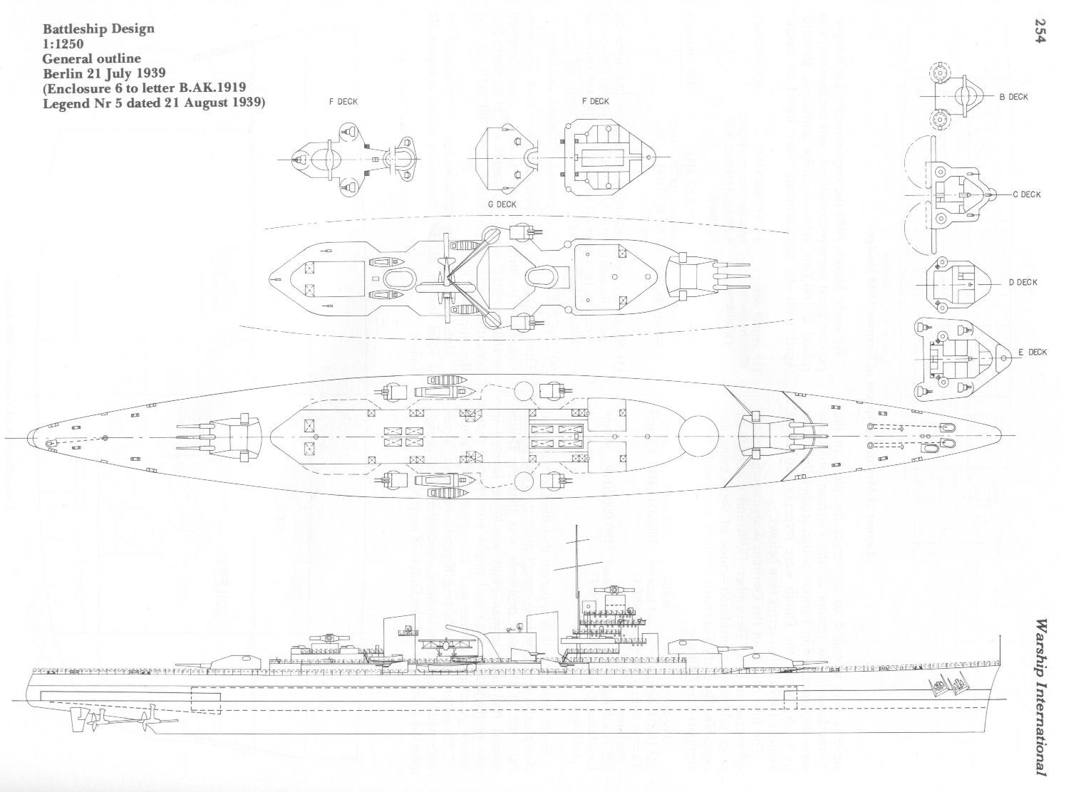 |
Battleship design - general outlin (Berlin 21 July 1939)
(Click on the drawing on the left. The link will open a new window) |
The German Admiral Bartenbach, who had been appointed as liaison between the Royal Netherlands and German Navies, stated on 4 October 1939 that although the delivery dates of the equipment to be ordered in Germany could not be guaranteed, they would not be interfered with by orders from the German Navy from the same firms and pressure would be put on them to meet the required dates. On 10 November 1939, Ferrostaal AG Essen was formally appointed to act on behalf of the Royal Netherlands Navy for all technical assistance and all equipment to be obtained from Germany. This arrangement did not include the Krupp armaments firm; all these contact would be dealt with directly between the Royal Netherlands Navy and Krupp.
Propulsion plant
The Royal Netherlands Navy formulated by late August 1939 the design requirements for the propulsion plant as follows:
| Propulsion power: 180.000 SHP |
| Eight boiler rooms, the boilers operating at 44 kg/cm2 and 400o C. |
| Four sets of geared turbines. |
From aft to forward the basic distribution was to be as follows (compartments separated by a central longitudinal bulkhead)
2 sets of geared turbines
4 boiler rooms
2 sets of geared turbines
4 boiler rooms
|
By early October 1939, the requirements had been refined somewhat and included a fully independent set of turbines (consisting of turbines for full speed, economical speed and reverse each) for each of the four shafts. Output per shaft was to be 45,000 SHP, providing 34 kts. speed at about 270 shaft RPM with a propeller diameter of about 4.75 meters. Boiler working pressure would be 40-42 kg/cm2 with at least 35-40 kg/cm2 at the turbines; boiler temperature remained at 400o C and coolant water temperature was to be 30o C.
Based on these requirements both the Royal Netherlands Navy/NEVESBU and Krupp Germaniawerft (turbines) and Deschimag (boilers) started work on a series of preliminary designs for the propulsion plant.
 |
Layout of Machinery Spaces of German 1939 design (reflecting Dutch requirements)
Click on the drawing on the left. The link will open a new window |
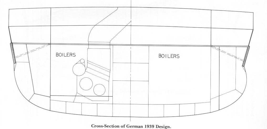 |
Cross-section of the German 1939 design (I)
Click on the drawing on the left. The link will open a new window |
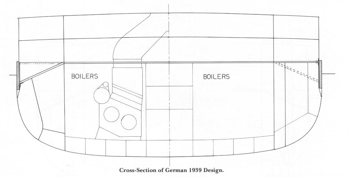 |
Cross-section of the German 1939 design (II)
Click on the drawing on the left. The link will open a new window |
However, from the beginning it was clear that in principle it was intended to construct the plant in the Netherlands. The results of the various German proposals were incorporated in various design studies drawn up by I.v.S., while the Dutch were incorporated in the Project 1047 design series (see below).
The first results of the German design studies were submitted in early December 1939, and a variety of proposals were considered . none of them being acceptable. By early February 1940 the proposed plants compared as follows:
| Project |
Boiler |
Output |
Area |
| 323 Dutch design |
Yarrow boilers/Parsons turbines operating at 44 kg/cm2 / 400o C |
180,000 SHP |
1209m2 |
| 323 IvS design |
Deschimag boilers/GW turbines operating at 44 kg/cm2 / 400o C |
180,000 SHP |
910m2 |
From this table it is apparent that the Germans had designed a much more compact plant than the Dutch, but one of the main problems was that the Dutch feared that the German plant would be located in too restricted an area and might not operate flawlessly. A major problem was that no more than about 72.80 meters of ship.s length could be made available which led to an impasse, since the I.v.S.-design needed 74 meters and the Dutch 78 meters.
By early March 1940 the requirements for the propulsion plant were reconsidered, and the question was raised if 160.000 SHP would be sufficient. By mid-April 1940 the requirements were listed as follows:
(1) North sea conditions
ca. 34 kts. |
4 x 45.000 SHP
specific steam output
3.50 kg/SHPh at 92%
vacuum |
630.000 kg/h |
(2) Tropic Water conditions
ca. 33 kts. |
4 x 40.000 SHP
specific steam output
3.60 kg/SHPh at 85%
vacuum |
575.000 kg/h |
| (3) Necessary steam production per hour for other purposes would be approximately 153.000 kg/h so that the boilers were to be designed for a specific steam output of 800.000 kg/h taking 2,2% reserve. |
| (4) The boilers would operate at 37 kg/cm2 and 380o C. |
This reduction in the required power took into consideration that theoretically a plant designed at 180.000 SHP in tropical waters would in North Sea conditions actually produce ca. 200.000 SHP, driving the ship at 34.8 kts.
Dutch estimates by early March 1940 provided for a total length of the propulsion plant complex as follows:
| Boiler room (2 boilers) |
10.50 meters |
| Boiler room (2 boilers) |
10.50 meters |
| Turbine room |
15.75 meters |
| Boiler room (2 boilers) |
10.50 meters |
| Boiler room (2 boilers) |
10.50 meters |
| Turbine room |
15.75 meters |
| Total |
73.50 meters |
The central longitudinal bulkhead originally required had by this time been abandoned as a result of the visit to Italy (see below).
On 20 April 1940 (drawing X 1c) the requirements had again been changed so far as required length was concerned.
| Centrale |
|
| No.1 Boiler room (2 boilers) |
8.25 meters |
| No.1 Boiler room (2 boilers) |
8.25 meters |
| No.1 Engine room |
15.00 meters |
| Centrale |
7.50 meters |
| No.3 Boiler room (2 boilers) |
8.25 meters |
| No.4 Boiler room (2 boilers) |
8.25 meters |
| No.2 Engine room |
15.00 meters |
| Total |
79.50 meters* |
| * Note webmaster: calculation adds up to 70,50. There is a discrepancy of 9 meters |
Armament
The basic requirements for the armament were discussed by representatives of the Royal Netherlands Navy and Krupp at Essen on 31 July 1939. The required characteristics at that time were as follows:
| (1) 28,3cm triple turret |
| Projectile weight |
ca. 300 kg |
| Initial velocity (v) |
850-900 m/s |
| Recoil |
ca. 250t per barrel |
| Max. elevation |
45o |
| Max. depression |
10o |
| Elevation |
hydraulic |
| Training |
electric |
| Ammo storage |
separate loading arrangements for projectiles (lower) and powder bags (upper). |
| Electrical power needed |
500 kW max.
260 kW average. |
| Armor |
front: 300mm
forward incline: 200mm
roof: 150mm
sides: 100mm
back: P.M.
barbette: 250 mm |
| Turret weight |
ca. 800 t |
| (2) 12 cm twin AA |
| Max. elevation |
80o |
| Max. depression |
10o |
| Armor |
front: ca. 80 mm
roof: ca. 150 mm
sides: ca. 50 mm
back: P.M. |
Fire control arrangements were discussed with the Dutch firm NV Hazemeyer Signaal Apparatenfabriek on 6 November 1939, and it appears that the following provisions were to be made.
| (1) 28cm battery |
| (a) |
one main fire control position forward (director control tower). |
| (b) |
one reserve fire control position aft (director control tower). |
| (c) |
one fire control position each in the superimposed forward turret and in the aft turret. |
| (d) |
Main and reserve fire control positions were to be fully identical with a 9 meter optical base with target and laying centers co-located in a turntable platform protected by an armored cupola; both would have an independent computing center. |
| (2) 12cm battery |
| |
Two fire control positions with a 3 meter optical base with target information and gun laying enters combined in a platform protected by an armored cupola. |
| (3) 40mm battery |
| |
To be controlled autonomously from the gun positions. |
Estimated unit cost
According to the preliminary cost estimates (undated) unit cost was assessed to be as follows (prices in DFL):
| (1) Shipbuilding |
| Hull |
975.000 |
| Armor |
15.625.000 |
| 160.000 SHP propulsion plant |
9.600.000 |
| Fittings (including catapult) |
6.396.750 |
| Trials & Insurance |
960.000 |
| Wages |
3.400.000 |
| Design & Drawings |
1.500.000 |
| Storage |
3.740.000 |
| Shipbuilding cost (w/o profit) |
42.196.750 |
| 6% profit |
2.531.805 |
| Total shipbuilding cost |
44,728,555 |
| (2) Armament |
| 3 28cm triple turrets |
10.500.000 |
| 28cm ammo (1080 rounds) |
1.350.000 |
| 28cm fire control |
750.000 |
| Optical rangefinders |
300.000 |
| 4 12cm twin turrets |
2.000.000 |
| 12cm ammo (1600 rounds) |
200.000 |
| starshells (100) |
35.000 |
| 12cm fire control |
1.400.000 |
| Optical rangefinders |
120.000 |
| 7 40mm twin mounts |
450.000 |
| Fire control |
400.000 |
| Optical equipment |
80.000 |
| 40mm ammo (14000 rounds) |
300.000 |
| 20 12.7mm twin mounts |
340.000 |
| 12.7mm ammo (30.000 rounds) |
50.000 |
| Reserve ammo (100%) |
1.935.000 |
| 2 additional 12cm twin turrets (including fire control and optics) |
1.160.000 |
| Total Armament cost |
21.370.000
|
| (3) Various equipment |
| Supplied by the Navy |
3.114.000 |
| Individual unit cost |
69,212,555 |
This cost estimate was of course preliminary and in the Naval Plan 1940-45 the total cost for three vessels was judged to be DFL 213,000,000. Payment was to be spread out as follows:
| Year |
DFL |
| 1940 |
30.600.000 |
| 1941 |
46.640.000 |
| 1942 |
48.635.000 |
| 1943 |
43.015.000 |
| 1944 |
27.310.000 |
| 1945 |
16.800.000 |
Note: Foreigh currency conversion rates during 1939 were as follows (approx.):
1 pound equalled DFL 8.75 (after 1 July 1939 DFL 7.50)
1 dollar equalled DFL 1.85
(Information supplied by Amsterdam Rotterdam Bank, 1978)
|
Detailed design work
The Construction Department (in collaboration with NEVESBU and the I.v.S.) started on detailed design work, based on the technical information obtained from German sources. The NEVESBU design series number was Project 1047, while I.v.S. called it Project 323. Project 1047 designs were fitted with Werkspoor/Yarrow propulsion plant while the I.v.S. Project 323 designs had the Deschimag/Germaniawerft propulsion plant. Detailed specifications of the various designs produced are listed under their separate headings.
I.v.S. Design activities
The I.v.S. independently started on design work for the battlecruisers based on information supplied by German firms and authorities, and taking into account the requirements formulated by the Royal Netherlands Navy. The first detailed design specifications, given in Table 3, were submitted for discussion with the Royal Netherlands Navy during mid-Noember 1939. These specifications are assumed to embody weight calculations from German sources but no specific record indicating this has been found.
| Table 3 - I.v.S. Project 323 November 1939 |
| Hull dimensions |
| Length at loaded waterline |
238.40 m |
| Beam at loaded waterline |
29.00 m |
| Draft at loaded waterline |
8.40 m |
| Moulded depth |
14.00 m |
| Displacement w/o attachments (loaded) |
31911.00 m3 |
| Displacement with attachments (loaded) |
32390.00 m3 |
| Displacement w/o attachments (loaded) |
32709.00 T |
| Displacement with attachments (loaded) |
33200.00 T |
| Midship section area |
231.50 m2 |
| Midship section coefficient |
0.95 |
| Block coefficient |
0.55 |
| Prismatic coefficient |
0.58 |
| Wetted surface w/o attachments |
7390.0 m2 |
| Weight distribution (metric tons) |
| I. Hull |
8931 |
| II. Armor (excluding revolving armor) |
11122 |
| III. Auxiliary equipment |
948 |
| IV. Main propulsion equipment |
2880 |
| V. Electrical |
524 |
| VI. Armament |
2992 |
| VII. Nautical equipment |
70 |
| VIII. Variable load |
5093 |
| IX. Margin (2%) |
640 |
| Normal load displacement |
33.200 |
| Washington displacement |
29.815 |
| Armor and protection |
| Main side belt |
250mm (5 meter deep), tapering to 60mm forward and aft. |
| Longitudinal bulkheads |
40mm |
| Citadel main transverse bulkheads |
225mm forward and aft |
| Citadel secondary transverse bulkheads |
40mm below 40mm armored deck |
| Main armored deck |
150mm |
| Splinter deck |
40mm (citadel area below main armored deck) |
| 28cm barbettes |
250 mm above main armored deck and 80 mm between main armored deck and splinter deck. |
| 12cm barbettes |
100 mm |
| Funnel and uptakes |
(395 tons) |
| Control positions |
(350 tons) |
| Armament |
| Armament |
9 x 28cm/50 in triple turrets (total supply 1350 rounds)
12 x 12cm/53 in twin turrets (total supply 2400 rounds)
16 x 40mm in twin mounts (total supply 16000 rounds)
16 x 13mm in twin mounts (total supply not indicated)
Catapult and 3 aircraft
100 depth charges |
| Machinery |
| SHP |
180.000 (4 x 45.000) |
| Speed |
34 kts (at 33,200 T displacement) |
| Fuel |
2700 tons |
| Notes: Unfortunately, no drawings have been found that relate to these proposals made during November 1939. These specifications provide the only detail on record of the calibre length of the 28cm and 12cm guns planned for the Dutch battlecruisers, and in doing so indicate that the 28cm guns planned for the Dutch ships were not the same as mounted in the German Gneisenau Class. |
The I.v.S. subsequently started on detailed hull design work, in which the last body plan produced dated 11 March 1940 showed the following characteristics.
| Table 4 - I.v.S. Project 323 Body Plan 11 March 1940 |
| Length between perpendiculars |
235.00m |
| Beam at DWL (outside armor) |
29.20m |
| Draft |
7.90m |
| Displacement w/o attachments |
29.340 m3 |
| Wetted surface w/o attachments |
7080 m3 |
| Midship section area |
217.70 m2 |
| Block coefficient |
0.541 |
| Midship section coefficient |
0.944 |
| Prismatic coefficient |
0.573 |
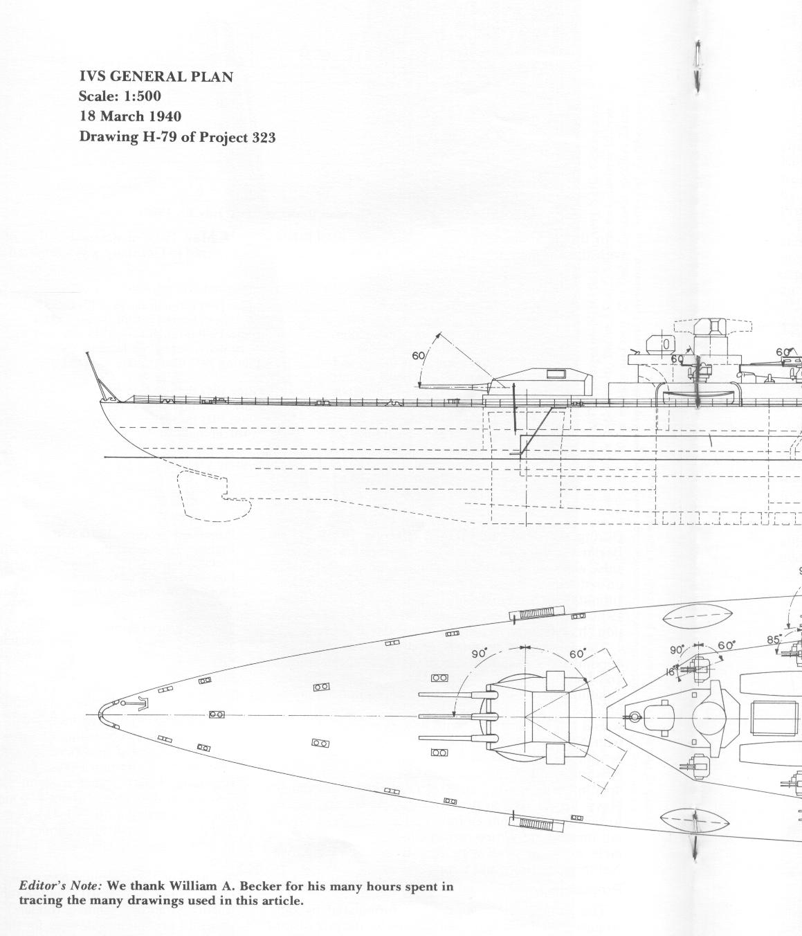 |
IVS General Plan (18 March 1940) - Drawing H-79 of Project 323 (I)
Click on the drawing on the left. The link will open a new window |
 |
IVS General Plan (18 March 1940) - Drawing H-79 of Project 323 (II)
Click on the drawing on the left. The link will open a new window |
 |
IVS General Plan (18 March 1940) - Drawing H-79 of Project 323 (III)
Click on the drawing on the left. The link will open a new window |
Design Work of the Royal Netherlands Navy
Although in autumn 1939 design work was well underway, and cooperation with Germany seemed reasonably assured, some reluctance on their part was still in evidence. Accordingly, Admiral Vos (Chief of the Materiel Department of the Navy) recommended strongly in a letter on 6 December 1939 to the new Navy Minister that the plans for the construction of the battlecruisers be brought before Parliament before Christmas 1939. However, the Navy Minister had not yet made up his mind as to exactly what type of vessel needed to be constructed. He apparently favored a 16.000 ton ship of the armored cruiser type. During December 1939, the Naval Construction Department considered the possibilities of such a ship and came to the comparison presented in Table 5.
| Table 5 - 16,000 Ton Project Armament & Protection Comparison |
| Displacement |
16.000 tons Washington |
| Speed: |
33 kts. in tropical waters. |
| Armament |
Protection |
Belt |
Deck |
Turret |
Torpedo bulkhead |
Three triple 28cm |
100 mm |
40 and 50 |
100 |
25 |
| Three twin 28cm |
120 |
50 and 60 |
120 |
30 |
| Three triple 24cm |
120 |
60 |
120 |
30 |
Three twin 24cm |
140 |
65 |
150 |
30 |
It was noted that if the armor protection proposed for the 27.000 ton project were to be worked into a 16.000 design, no armament could be fitted. Also, it was considered that the plans for the former could be completed in 5 to 5,5 months, while if the Navy had to revert to a 16.000 ton design, a delay of 6 months was expected. A memorandum was drawn up on 11 December 1939 in which it was stated that on a 16.000 ton displacement, a design could be prepared with characteristics shown in Table 6.
| Table 6 - 16.000 Ton Armored Cruiser |
| Displacement |
16,000 tons Washington |
| Dimensions |
ca. 200 x 25 x 12 x 6,75 meters. |
| Armament |
3 triple 24cm
4 twin 12cm
8 twin 40mm
several smaller guns |
| Protection |
| Belt |
175mm |
| Deck |
75mm |
| Turrets |
200mm (24cm) and 60mm (12cm) |
| Torpedo bulkheads |
30mm |
| Propulsion |
| SHP |
90.000 |
| Speed |
29 kts. (28 kts. in tropical waters) |
| Weight |
1750 tons |
| Note: Unfortunately, no sketch drawing (or any reference thereto) has been found. |
It was appreciated that this vessel would be superior to a 20cm 10.000 ton cruiser, but had the important weakness that it could not avoid action with stronger opponents due to inferior speed. The protection also was felt to be insufficient. Consequently, the Navy strongly recommended against the construction of such a ship and nothing more was heard about the project.
In the meantime the German firms Deschimag and Germaniawerft started on detailed design work for the battlecruisers. propulsion plant. It is clear from the files that great problems were encountered in putting the required power into a ship of this size and still have a balanced design. Although the Germans succeeded rather better than the Dutch in limiting the area needed as much as possible, the Netherlands Navy remained to the end sceptical about using the rather complicated German plant. The Dutch feared that they would not have the necessary highly qualified personnel and overhaul capabilities available in the Netherlands East Indies if something went wrong with the plant. Therefore, they continued to prefer their own licensed built Werkspoor (Yarrow) boilers and Parsons turbines.
An undated tentative delivery schedule of about late 1939 was as follows:
| Unit |
Keel laid |
Commissioning |
| 1 |
1 February 1940 |
1 February 1944 |
| 2 |
1 July 1940 |
1 July 1944 |
| 3 |
1 December 1940 |
1 December 1944 |
During the fall of 1939, the Naval Construction Department, in collaboration with NEVESBU (and probably with the technical advise of the I.v.S.) worked out the detailed design specifications shown in Table 7.
| Table 7 - Project 1047: Ca. October 1939 |
| Hull Dimensions |
A |
B |
C |
| Length at DWL (trial displacement) |
230.00 m |
235.00 m |
240.00 m |
| Length at loaded waterline |
|
235.60 m |
|
| Beam at DWL |
30.00 m |
30.00 m |
30.00 m |
| Draft at DWL (trial displacement) |
7.80 m |
7.80 m |
7.80 m |
| Draft at loaded waterline |
|
8.15 m |
|
| Moulded depth (ships. side) |
14.00 m |
14.00 m |
14.00 m |
| Moulded depth (centreline) |
|
14.30 m |
|
| Displacement w/o attachments (trial displacement) |
28.223.00 m3 |
28.283.00 m3 |
28.223.00 m3 |
| Displacement with attachments (trial displacement) |
28.811.00 T |
29.251.00 T |
28.811.00 T |
| Displacement w/o attachments (load displacement) |
|
29.924.00 m3 |
|
| Displacement with attachments (load displacement) |
|
30.890.00 T |
|
| Midship section area (trial) |
|
212.71 m2 |
|
| Midship section area (loaded) |
|
223.21 m2 |
|
| Wetted surface with attachments |
|
7340.00 m2 |
|
| Midship section coefficient |
|
0.909 |
|
| Block coefficient |
|
0.514 |
|
| Waterline coefficient |
|
0.665 |
|
| Prismatic coefficient |
|
0.565 |
|
| Note: The 3 variants were developed to determine the most favourable dimensions and form coefficients. Variant B subsequently was selected to undergo towing trials at the towing tank at Wageningen (see below) and apparently was sused as a basis for all further work. |
| Weigh distribution (Variant B) in Metric Tons |
| I. Hull |
7518.15 |
| II. Armor (excluding revolving) |
10620.00 |
| III. Auxiliary equipment |
888.00 |
| IV. Main propulsion equipment |
2972.00 |
| V. Electrical |
524.00 |
| VI. Armament |
3087.00 |
| VII. Nautical equipment |
70.50 |
| VIII. Variable load |
4946.36 |
| IX. Margin |
263.59 |
| Normal load displacement |
30890.00 T |
| Washington displacement (1.1016) |
27940.00 t |
| Empty ship |
26489.08 T |
| Armor Protection (as taken from Drawing Z 1 dated 27 October 1939) |
| Main side belt (waterline) |
225mm on 50mm teak backing, located internally at 75o angle. |
| Upper side belt |
60mm tapering upwards to 30mm, angled at 75o. |
| Longitudinal bulkhead |
40mm |
| Main armored deck |
75mm + 25mm |
| Upper armored deck |
30 mm |
| Note: Other details unknown |
| Armament |
| Guns |
9 x 28cm in triple turrets (120 rounds per gun)
12 x12 cm in twin turrets (200 rounds per gun)
16 x 40mm in twin mounts (1000 rounds per gun)
20mm or 12.7mm guns
2 aircraft |
| Machinery |
| SHP |
180.000 |
| Speed |
34 kts. |
| Fuel |
2700 tons. |
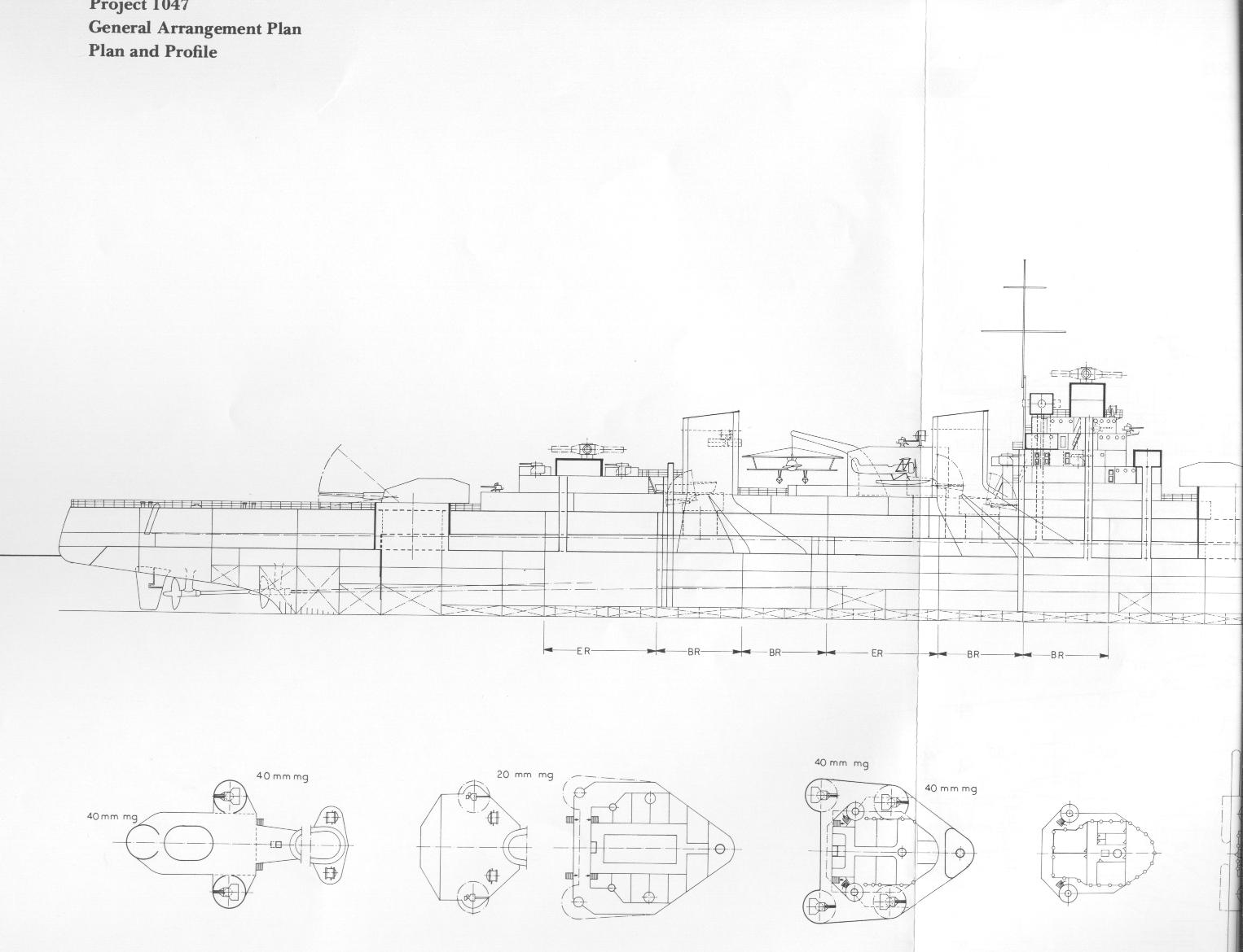 |
Project 1047 - General arrangement plan and profile (I)
This drawing gives an cross-section overview of armor distribution.
(Click on the drawing on the left. The link will open a new window) |
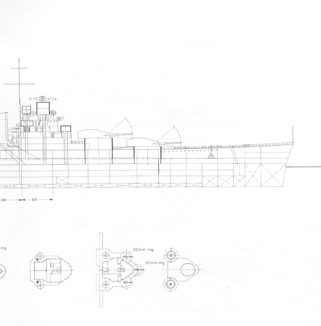 |
Project 1047 - General arrangement plan and profile (II)
This drawing gives an cross-section overview of armor distribution.
(Click on the drawing on the left. The link will open a new window) |
Internal Arrangements
Accommodation of the propulsion plant was one of the main problems to be solved in the design, as has been seen above. Initially, about 84 meters ship.s length were assumed to be available, but it soon became apparent that this would not do if the ammunition supply was to be stored behind armor. During the succeeding months, after various schemes had been proposed, it was theoretically decided in March 1940, to fix the citadel length as follows:
| Aft turret complex |
ca. 17.25m |
| Aft electrical power station, computing center and pumping space |
ca. 6.00m |
| Aft engineroom |
ca. 15.75m |
| Aft boiler rooms (2 x 10.50m) |
ca. 21.00m |
| Forward engineroom annex power station and pumping space. |
ca. 15.75m |
| Forward boiler rooms (2x x 10.50m) |
ca. 21.00m |
| Forward electrical power station and pumping space |
ca. 6.00m |
| Various centers |
ca. 6.00 m |
| Forward turret complex |
ca. 31.50 m |
| Total citadel length |
ca. 153.50m |
Even this arrangement was not considered final because it was still not possible to provide sufficient protection to the ammunition storage. It is not apparent from the record if this problem was ever satisfactorily solved.
Model Trials
During February 1940 (or perhaps already at a much earlier date) model trials were held with the Variant B of the Naval Construction Department Design 1047 at Wageningen. Apparently, two models were tested: a Model No. 367 with a normal bow, and a Model No. 367A fitted with a bulbous bow. The characteristics of the ships representing the models would have been as follows according to the trial result report of 19 February 1940.
| |
Model 367 |
Model 367A |
| Length between pp. |
235.00 |
235.00 |
| Length at waterline (trial) |
235.00 |
237.10 |
| Beam at waterline (trial) |
30.00 |
30.00 |
| Mean draft (trial) |
7.80 |
7.80 |
| Displacement on frames |
28283 |
28318.5 |
| Displacement in salt water (1.025) |
28990 |
29026 |
| Wetted surface (naked) |
6664 |
6686 |
It appears that the bulbous bow variant was considered the more satisfactory of the two, since the characteristics of Project 1047 as listed on Drawing Z-6 of 9 February 1940 reflect those measurements.
New weight calculations
During the period November 1939 through February 1940 some detailed work was done on the weight problem. A number of weight summaries were produced, unfortunately all undated. They are summarized below:
| Table 8 - Project 1047 Weight Distribution |
| |
|
(i) |
(ii) |
| I. Hull |
|
7080.359 |
7366.499 |
| II. Armor (excluding revolving) |
|
11216.738 |
11119.037 |
| Belt (including bolts & wood) |
2850.018 |
|
|
| Upper deck |
908.643 |
|
|
| Main deck |
2630.580 |
|
|
| Longitudinal bulkheads |
891.378 |
|
|
| Transverse bulkheads |
233.912 |
|
|
| 28cm barbettes |
969.087 |
|
|
| 12cm barbettes |
188.690 |
|
|
| Control positions, etc. |
296.951 |
|
|
| Other |
2247.479 |
|
|
| III. Auxiliary equipment |
|
937.752 |
937.752 |
| IV. Main propulsion equipment |
|
2936.350 |
2936.350 |
| 4 propellers, shafts, etc. |
394.350 |
|
|
| 4 turbine sets, etc. |
975.000 |
|
|
| 8 boilers, etc. |
852.000 |
|
|
| Other |
715.000 |
|
|
| V. Electrical |
|
540.000 |
540.000 |
| VI. Armament |
|
3010.498 |
3012.000 |
| three 28cm turrets incl. armor |
2232.000 |
|
|
| eight 12cm turrets |
348.000 |
|
|
| seven 40 mm twin AA |
38.500 |
|
|
| eight 20 mm single AA |
9.600 |
|
|
| 2 sets paravanes |
4.500 |
|
|
| 3 sets smoke makers |
11.000 |
|
|
| Searchlights (dia. 1500mm) |
8.000 |
|
|
| Searchlights (dia. 1200mm) |
1.500 |
|
|
| Fire control |
150.000 |
|
|
| Catapult |
25.000 |
|
|
| Other |
182.398 |
|
|
| VII. Nautical equipment |
|
36.650 |
36.650 |
| VIII. Variable load |
|
4955.140 |
4955.140 |
| Complement |
172.940 |
|
|
| Provisions |
103.500 |
|
|
| Washwater |
110.000 |
|
|
| Drinking water |
99.000 |
|
|
| Feed water |
177.000 |
|
|
| Fuel oil |
2684.100 |
|
|
| Diesel oil |
84.000 |
|
|
| Other liquids |
264.500 |
|
|
| 28cm ammo (1080 rounds) |
523.800 |
|
|
| 12cm ammo |
96.000 |
|
|
| 40mm ammo |
46.200 |
|
|
| Machine gun and rifle |
16.000 |
|
|
| Other explosives |
24.000 |
|
|
| Chemical |
2.000 |
|
|
| Aircraft & Equipment |
7.000 |
|
|
| Water & oil in boilers and engines |
440.000 |
|
|
| Water & oil in piping |
35.000 |
|
|
| Various loads & ammo |
88.100 |
|
|
| Total |
|
30713.717 |
30903.528 |
No detailed specifications for (ii) have been found. They do exist for (i) and it is assumed that (i) is the latter of the two, possibly giving the state of affairs as of about February 1940.
First Finalized Design
Probably as a result of the model test findings and other considerations (which unfortunately can no longer be exactly reconstructed due to the lack of reference material) Project 1047 came to some finalization by February 1940. At the least, a large number of detailed drawings were produced during this time, giving the particulars shown in Table 9.
| Table 9 - Project 1047 (February 1940) |
| Displacement & Dimensions |
Source |
| Length at DWL (trial) |
237.10 m |
Drawing Z 6 (11 Feb. 40) |
| Length between pp |
235.00 m |
Model test 367A |
| Maximum beam |
30.44 m |
Drawing Z.1 (27 Feb. 40) |
| Beam at DWL (trial) |
30.00 m |
Drawing Z.1 (27 Feb. 40) |
| Mean draft (trial) |
7.80 m |
Drawing Z.1 (27 Feb. 40) |
| Moulded depth |
14.00 m |
Drawing Z.1 (27 Feb. 40) |
| Trial displacement |
28315.5 T |
Drawing Z 6 (11 Feb. 40) |
| Armament |
No. of guns |
|
| 28cm in triple turrets |
9 |
Drawing X 4 (16 Feb. 40) |
| 12cm in twin turrets |
12 |
Drawing X 4 (16 Feb. 40) |
| 40mm in twin mounts |
14 |
Drawing X 4 (16 Feb. 40) |
| 20mm in single mounts |
8 |
Drawing X 4 (16 Feb. 40) |
| (Aircraft & catapult not included) |
|
|
| Armor & Protection |
Drawing Z 1 (27 Feb. 40)
Drawing D1b (10 Feb. 40) |
| Main side belt |
225mm inclined at 75o (on 50mm teak with 18mm shell plating) |
| Upper side belt |
40mm inclined at 75o |
| Side belt forward |
30mm tapering forward to 15mm |
| Side belt aft |
30mm upper, 60mm lower |
| Longitudinal anti-torpedo bulkheads |
40mm |
| Depth of main side belt |
5.35m (2.10m below DWL, 3.25m above DWL) |
| Main armored deck |
75mm + 25mm |
| Lower deck |
30mm with 30mm inclines |
| Boiler uptakes |
225mm gratings (main deck) and 75mm gratings (lower deck) |
| Lower deck aft |
125-150mm protecting steering gear and propellers. |
| Transverse bulkheads |
30mm + 15mm secondary forward. 200mm tapering to 40mm below main forward and aft |
| 28cm barbette |
250-200mm tapering to 40mm below |
| 12cm barbette |
75mm tapering to 60 mm |
| Turret armor |
Not indicated |
| Conning tower |
150 mm |
| Underwater protection |
Double bottom depth 1.50m. Depth of side protective system 5.35m. Height of bulge compartment 9.60m. System consisting of air space-fluid air space compartments. |
| Machinery |
| SHP |
ca. 180000 |
| Speed |
34 kts. |
| Radius |
4500 NM at 20 kts. |
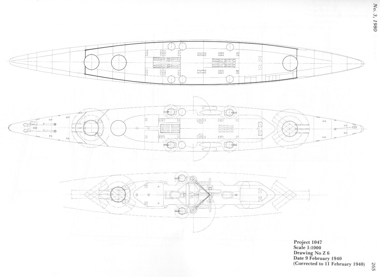 |
Drawing Z6 dated 9 February 1940 (design 1047 by NEVESBU)
This drawing gives an overview of armament lay-out and the ships' general profile.
(Click on the drawing on the left. The link will open a new window) |
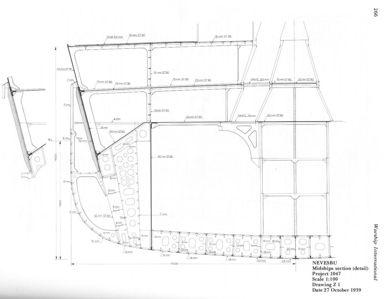 |
Drawing Z1 dated October 27 1939 (I) (design 1047 by NEVESBU)
This drawing gives a cross-section overview of armor distribution.
(Click on the drawing on the left. The link will open a new window) |
 |
Drawing Z1 dated October 27 1939 (II) (design 1047 by NEVESBU)
This drawing gives a cross-section overview of armor distribution.
(Click on the drawing on the left. The link will open a new window) |
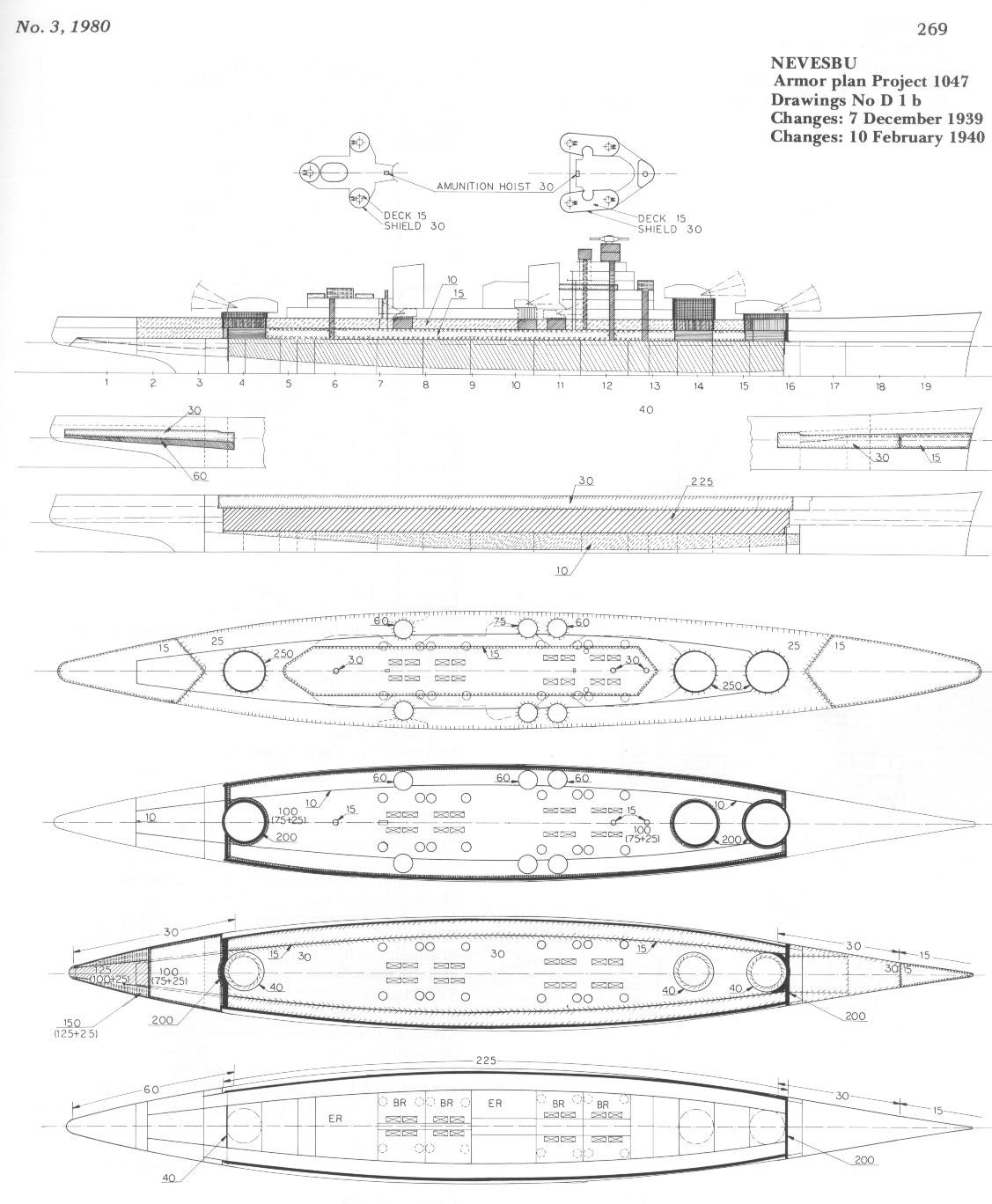 |
Drawing D 1 b (I) dated 10 February 1940 (design 1047 by NEVESBU)
This drawing gives profile overview of armor distribution.
(Click on the drawing on the left. The link will open a new window) |
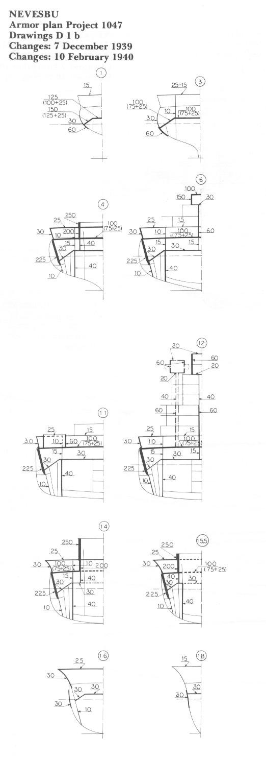 |
Drawing D 1 b (II) dated 10 February 1940 (design 1047 by NEVESBU)
This drawing gives cross-section overview of armor distribution.
(Click on the drawing on the left. The link will open a new window) |
Further activities
During February 1940, apparently for the first time since the preliminary design had been drawn up in July 1939, serious attention was given to the idea of placing the side armor externally rather than internally (Table 9 still reflects internal side armor). So far, the detailed design drawings that can be located all gave the main belt in an internal position. However, according to a note dated 23 February 1940, the design drawing on this matter with external side armor was completed on that date. The final decision in this matter was postponed to study the outcome of a visit to Italy and the results of further talks with the Germans during February through April 1940.
Factfinding mission to Italy
The Dutch delegation visited the battleship Vitterio Veneto but were not allowed on board the Roma which was still under construction. The important result of this visit was that it was felt necessary to completely redesign the inner subdivision of Project 1047. The findings of the visit to Italy and further consultation with the Germans were discussed in project meetings during March and April 1940 in Holland, representatives of the Naval Construction Department and of the I.v.S. taking part. Unfortunately, only shorthand pencil notes appear to survive from these meetings, which can no longer be fully interpreted. However, the following points were noted:
(a) The central longitudinal bulkhead between the engine rooms was to be eliminated.
(b) The Italian suggestion to heighten the double bottom was considered very valid . especially with regard to the expected threat of future magnetic torpedoes . and some thought was given to the possibility of adding a second double bottom at 3 meters from the baseline (keel) with 25mm armor. However, it was found that the relatively shallow draft of the vessel would not permit this.
It was then decided to send a mission to Germany to talk over the problems again. This delegation took the design particulars, given in Table 10, dated 19 April 1940 along, which appears to represent the last design stage reached before the outbreak of war.
| Table 10 - Project 1047 (19 April 1940) |
| Hull |
| Length between pp (at DWL) |
236.00m |
| Length oa |
241.20m |
| Maximum beam at DWL (outside armor) |
29.40m |
| Maximum beam (upper deck) |
30.85m |
| Moulded depth |
14.00m |
| Trial draft |
7.80m |
| Trial displacement (incl. armor) |
28829.00m3 |
| Trial displacement (incl. attachments) |
29029.00m3 |
| Trial displacement |
29784.00 T |
| Normal load displacement |
31396.00 T |
| Washington displacement |
27988.00 t |
| Midship section area |
216.20 m2 |
| Midship section coefficient |
0.943 |
| Block coefficient |
0.5326 |
| Prismatic coefficient |
0.5648 |
| Waterline coefficient |
0.642 |
| Stability |
| Center of gravity |
ca. 9.10m |
| Center of buoyancy |
4.23m |
| Metacenter |
11.89m |
| M . G |
ca. 2.79m |
| Machinery |
See chapter Propulsion plant |
| Armor & protection |
(Drawing Z-17 dated 10 April 1940) |
| Main side belt |
225mm inclined at 72o (on 50mm teak with 17mm shell plating), external. |
| Upper side belt |
40mm (vertical) |
| Longitudinal anti-torpedo bulkhead |
40mm |
| Depth of main side belt |
5.30m (2.10m below DWL, 3.20m above DWL) |
| Upper deck |
20mm (?) |
| Main armored deck |
100mm on 15 (?)mm deck plating |
| Lower deck |
30mm with 30mm inclines |
| Boiler uptakes |
225mm gratings (main deck) and 75mm gratings (lower deck) |
| Underwater protection |
Bulge compartment below main side belt (depth 1.50 (?)m; double bottom depth 1.65m |
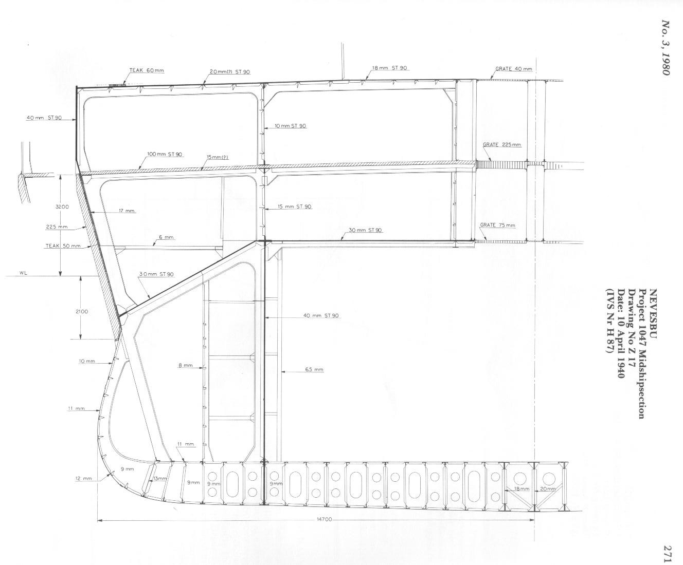 |
Drawing Z-17 dated 10 April 1940 (design 1047 by NEVESBU)
This drawing gives an cross-section overview of armor distribution.
(Click on the drawing on the left. The link will open a new window) |
Note: On 8 april 1940 a variant midship section also had been produced (Drawing Z-15) which included an internal side belt and showed the following differences with the data listed in Table 10.
| Maximum beam at DWL |
29.40m |
| Maximum beam (upper deck) |
29.40m |
| Main side belt |
225mm probably inclined at 72o (on 50mm teak with 17mm shell plating), internal. |
| Upper side belt |
40mm probably inclined at 72o |
| Longitudinal anti-torpedo bulkhead |
40mm |
| Depth of main side belt |
5.55m (2.25m below DWL, 3.30m above DWL) |
| Upper deck |
60mm teak on 30mm armor plating |
| Main deck |
100mm on 13mm deck plating. |
| Lower deck |
Estimated 30mm with 30mm inclines |
| Boiler uptakes |
Not indicated |
| Underwater protection |
Depth of side protective system 5.55m, depth of bulge 3.75m, system consisting of empty tank . empty tank . liquid tank. |
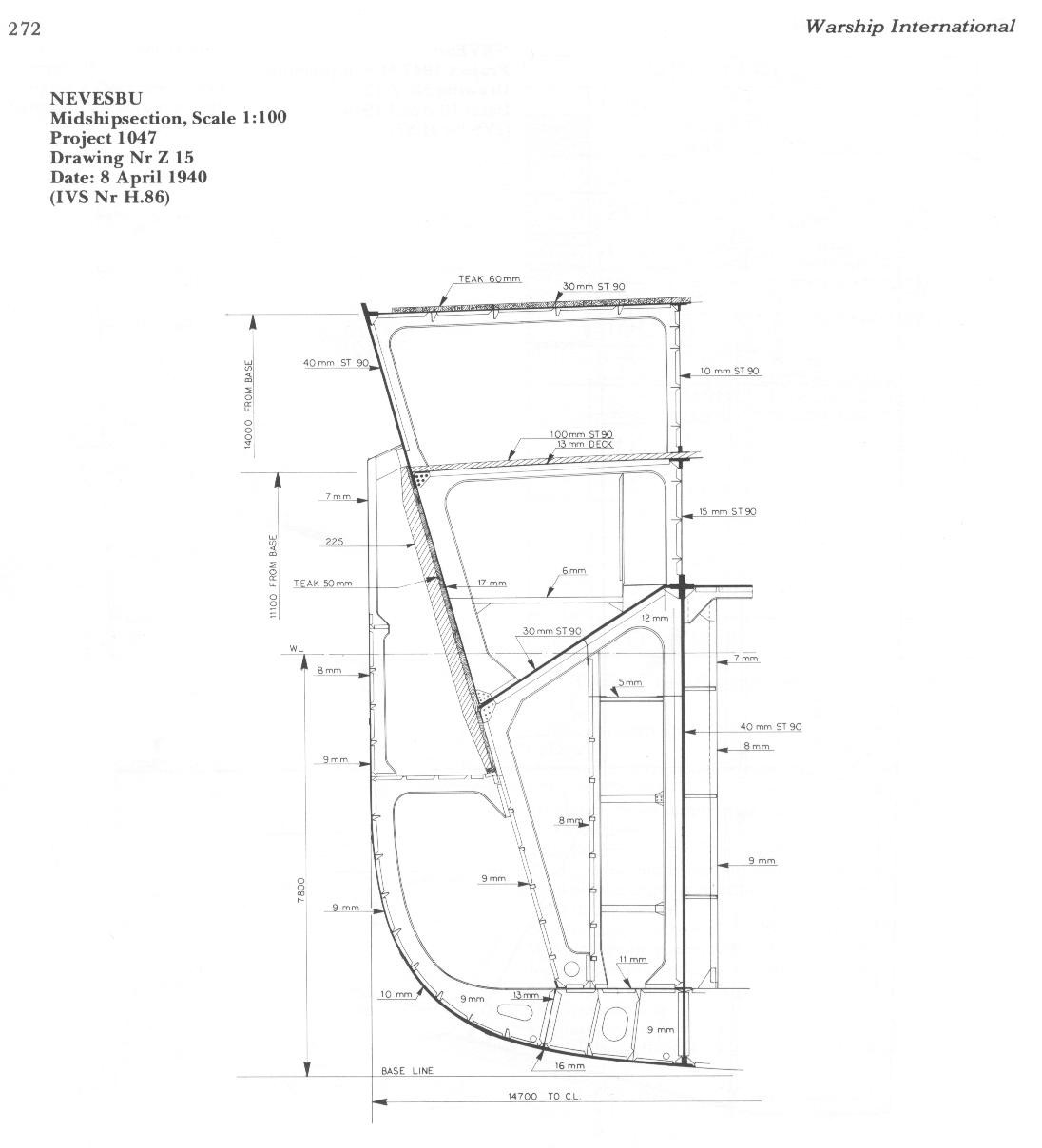 |
Drawing Z-15 dated 8 April 1940 (design 1047 by NEVESBU)
This drawing gives an cross-section overview of armor distribution.
(Click on the drawing on the left. The link will open a new window) |
About the author
J.S. Noot, LT Royal NL Navy
Lt. Noot is 33 years old, married with no children. He entered the navy in 1966 and was commissioned as a lieutenant j.g. in 1968, and spent some time serving on board Hr.Ms. Karel Doorman. After that, he was posted to the Ministry of Defence in The Hague as research analyst, in which capacity he is still employed. His main hobby is the study of naval ships since the introduction of steam, and over the years has collected a vast amount of books and other material on the subject. He joined our organization 6 years ago, but has been fortunate in taking over from a deceased person an almost complete collection of all the W.I. issues that have appeared since it was first published. He is also a member of the World Ship Society.
- End of article -
Note by webmaster
This article is a reproduction of the original article published in Warship International No.3 of 1980. Alterations of the original article have only been made with regards to the lay-out and some photo descriptions, the contents are otherwise original. This article does not include new facts which may have come to light since the article's publication in 1980.
This article is reproduced with the kind permission of Warship International. Copyright © 1980 International Naval Research Organization (http://www.warship.org)
|